
Solar Inverter
How to set inverter for 24 hour backup

How to Set Inverter for 24 Hour Backup: A Step-by-Step Guide
lackout-proof your home. Learn how to set your inverter for a 24-hour backup with this quick, expert guide on load, battery settings, and setup.”
Power outages bring household appliances to a halt, spoil food, and cause businesses to face data loss and production disruptions. These interruptions create significant inconvenience and economic losses that could be avoided with proper preparation.
Learning how to set inverter for 24 hour backup solves this problem. A typical household requires 24kWh of battery capacity to maintain 1kWh to 2kWh/hour consumption throughout the day.
In this guide, we’ll walk you through calculating your power needs, installing the system, configuring settings, and troubleshooting common issues to keep your power always on.
Understanding 24 Hour Backup Inverter System Components
What is a 24 Hour Backup Inverter
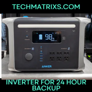
A 24-hour backup inverter system stores electrical energy in batteries and converts it into usable household power when the grid fails. The system charges its battery bank when grid electricity is available, then switches to battery power during outages to continue supplying electricity to connected devices. This conversion happens through an inverter that changes direct current (DC) from batteries into alternating current (AC) that powers your appliances.
The switching process occurs within a very short time frame, preventing noticeable interruptions to your equipment. When grid power returns, the system automatically resumes charging while maintaining power to your devices through controlled recharge cycles that prevent overheating and overcharging.
Key Components You’ll Need
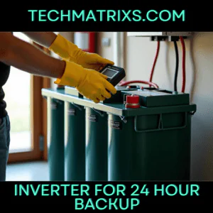
- Every backup system requires specific components working together. The battery forms the basic building block, containing a cathode (positive terminal), anode (negative terminal), and an electrolyte that promotes ion movement to create current flow. Individual cells combine into modules, which then form trays that may include their own Battery Management System.
- The Battery Management System protects batteries from damage by monitoring state of charge, voltage, current, and temperature. It records electrical operating parameters, electrolyte levels, internal cell temperature, and ambient battery enclosure temperature. This monitoring becomes particularly critical for lithium-ion batteries, which accounted for more than 90% of global investment in battery energy storage in 2020 and 2021.
- The inverter converts DC power from batteries into AC power for household use. Hybrid inverters manage power from multiple sources like solar panels, battery banks, and backup generators, directing it to appliances or batteries as needed. These devices can operate bidirectionally, allowing power to flow from DC to AC or vice versa for charging and discharging.
- A charge controller regulates how batteries receive power, while control circuits monitor power flow between energy sources and loads. These circuits track battery charge state, grid voltage and frequency, and solar panel output to make decisions about charging, discharging, and optimizing solar power use.
- To Read more Aritcles this type Click Here
Types of Inverters for Backup Systems
- Standalone inverters connect one end to batteries and the other directly to loads. They work independently from the public grid without synchronization functions, making them suitable for off-grid applications. When planning how to hook up a 12v inverter to a 24v system, you’ll need batteries configured to match your inverter’s input voltage requirements.
- Hybrid inverters combine standalone and grid-tied functions, managing current flow between solar systems, batteries, and the public grid. They inject excess solar capacity into the grid for compensation when power is sufficient, then switch to battery or grid power when the system cannot carry the full load. During grid outages, hybrid inverters automatically switch to battery power mode while disconnecting from the grid to prevent back-feeding electricity.
- The waveform output separates inverter types further. Pure sine wave inverters replicate the smooth, continuous oscillation from utility companies with Total Harmonic Distortion below 3%. They operate at 90% to 95% efficiency, making them suitable for sensitive electronics and induction motors.
- Modified sine wave inverters create a stepped approximation with THD between 20% to 30%. While cheaper to manufacture, they only reach 75% efficiency and cause motors to run 20% less efficiently while producing audible humming. The efficiency difference means you drain batteries faster to accomplish the same work, reducing available backup time during emergencies.
Calculating Your Power Requirements and Battery Capacity
Selecting the right inverter type means nothing without properly sizing your battery bank to deliver 24 hours of continuous power. The calculations require precision to avoid undersized systems that fail during outages or oversized banks that waste money.
Determine Your Daily Power Consumption
Start by listing every appliance you plan to run during an outage. Find each device’s wattage on its nameplate, compliance label, or user manual. When wattage isn’t listed directly, multiply voltage by amperage to get watts. A refrigerator might draw 200W, while a laptop consumes 65W.
Calculate each appliance’s daily consumption using this formula: Daily kWh = (Wattage × Hours Used) ÷ 1000. For instance, a 40-watt CPAP machine running 8 hours nightly consumes 320 watt-hours daily. An oxygen concentrator drawing 300 watts for 8 hours requires 2,400 Wh.
Duty cycles matter for accurate estimates. Refrigerators, freezers, and HVAC systems don’t draw their full rated wattage constantly. A 200-watt refrigerator cycling 8 hours at 33% duty actually consumes 48 kWh monthly, not the inflated figure you’d get from continuous operation. Ignoring these patterns leads to oversized, expensive systems.
Add phantom loads from devices in standby mode. Your router and television draw power even when “off,” contributing to average daily consumption. Sum all appliance watt-hours to establish your total daily demand.
Calculate Required Battery Capacity
Battery capacity calculations use this formula: Battery Capacity = Backup Hours × Daily kWh × DoD Factor. The DoD (depth of discharge) factor accounts for how much capacity you can safely use. Lead-acid batteries utilize only 50% of rated capacity. Tubular lead-acid reaches 60%, while lithium-ion allows 80% and LiFePO4 permits 90% discharge.
A home consuming 2,000 watts for 24 hours needs 48,000 watt-hours of total load. With lead-acid batteries at 50% DoD, you’d need a 96 kWh bank. Lithium batteries at 80% DoD reduce this to 60 kWh.
Convert watt-hours to amp-hours using: Battery Capacity (Ah) = Total Daily Energy Consumption (Wh) ÷ Battery Voltage (V). When learning how to hook up a 12v inverter to a 24v system, this calculation determines whether series or parallel battery configurations meet your capacity needs. A 10,000 Wh daily load on a 48V system requires 208 Ah.
Account for inverter efficiency by dividing total power by the efficiency rating. At 90% efficiency, a 2,600W requirement becomes 2,889W. The backup time formula verifies your sizing: Backup Time = (Battery Capacity × Battery Voltage × Efficiency) ÷ Total Load. A 150 Ah, 12V battery at 90% efficiency powering 300W provides 5.4 hours.
Choosing the Right Battery Type
Battery chemistry determines usable capacity and system cost. Lead-acid batteries operate at 80-85% efficiency, meaning 1,000 watts of solar input yields only 800-850 watts after charging and discharging. Lithium batteries exceed 95% efficiency, delivering over 950 watts from the same input.
Lithium batteries charge faster by handling higher amperage from chargers. Their deeper discharge capability means lithium banks require only 50-60% the size of comparable lead-acid systems. A lead-acid bank needing 200 kWh shrinks to 100-120 kWh with lithium.
Cycle life extends dramatically with lithium chemistry. Lead-acid batteries must be fully recharged daily to prevent damage, while lithium tolerates partial charge states without adverse effects. Temperature sensitivity also differs, with lead-acid performance degrading faster in cold conditions compared to lithium’s broader operating range.
Installing and Connecting Your Inverter System
Proper installation transforms your calculated battery capacity into a functional backup system. The physical setup requires attention to location, wiring methods, and safety protocols that directly impact system performance and longevity.
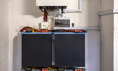
Positioning Your Inverter and Batteries
Install your inverter and batteries indoors in a well-ventilated, cool, dry environment. Locations must remain free from moisture, rain, snow, and any liquids. The area cannot contain flammable materials, gasses requiring ignition-protected equipment, gasoline-powered machinery, or fuel tanks.
Specifically, position components where the inverter’s on/off switch and AC outlets remain accessible. Secure the inverter to a stable surface with several inches of clearance for airflow around the unit. Mount batteries directly or partially below the inverter when space allows. The installation surface must support the combined weight for extended periods and consist of non-flammable materials.
Ensure adequate free space for ventilation above and below the product, checking that ventilation vents stay unblocked. Battery compartments require ventilation as batteries generate hydrogen and oxygen during charging, creating explosive gas mixtures.
Wiring the Battery Bank to Inverter
Wire gage selection depends on maximum power delivery and cable length. Use 2AWG cables for battery-to-battery connections and 2/0 AWG cables for inverter-to-battery bank connections. All wiring must be stranded, insulated copper (OFC – Oxygen Free Copper).
Connect batteries following the correct parallel configuration to prevent premature failure. The common mistake involves paralleling all batteries together, then connecting one side to the installation. This creates unequal current paths where bottom batteries work harder than top batteries.
The correct method ensures equal total current paths in and out of each battery:
- Connect the negative cable from your charge controller and inverter to the negative terminal at one end of the battery bank
- Connect the positive cable from your charge controller and inverter to the positive terminal at the opposite end of the battery bank
- Use proper jumper wires between batteries to maintain parallel connections
- Verify all negative connections terminate at one battery bank end and all positive connections at the other
Install a sealed battery protection fuse within 12 inches of the positive battery terminal. This safety fuse prevents battery explosions if cables short. Size the fuse by dividing AC output watts by 10; a 400-watt inverter requires a 40-amp fuse.
Connecting to Your Home’s Electrical Panel
You have three installation approaches. The sub-panel method places a breaker in your main electrical panel feeding to your inverter, which then feeds a panel of breakers rated for the inverter’s maximum pass-through capacity. The whole house approach wires the inverter with appropriate amperage pass-through directly inline with incoming power.
Installation and wiring must comply with local and national electrical codes and requires a certified electrician.
Safety Precautions During Installation
Always connect the grounding terminal on the unit to the appropriate grounding system. Disconnect all AC and DC connections before working on circuits associated with the unit. Wait at least 5 minutes after disconnecting power before performing work, allowing internal components to discharge.
Remove metal items like rings, bracelets, and watches when working with batteries, as they can produce short circuits severe enough to weld metal and cause burns. Use safety gloves when connecting batteries and ensure cable ends never touch.
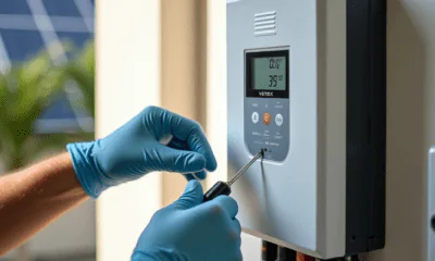
Configuring Inverter Settings for 24 Hour Backup
Configuration determines whether your installed system delivers reliable 24-hour backup or fails during critical moments. Access your inverter’s settings through the LCD panel, mobile app, or VEConfigure software depending on your model.
Setting Battery Charge Parameters
Select your battery type first, as this triggers preset charging profiles. For lithium batteries, choose “LiFePO4 Mode” or enter custom values in “User Mode”. Specifically, a 24V LiFePO4 system requires charging limit voltage at 29.2V, float charging voltage at 27.6V, and boost charging voltage at 27.6V.
Set the absorption voltage where batteries are held at constant target voltage with variable current. For lead-acid batteries, use approximately 14.2V per cell. Float voltage provides reduced voltage to trickle charge without creating excess heat or gassing.
Configure charge current limit during the bulk phase. Lead-acid batteries need charging current at 10 to 20% of battery capacity. A 200Ah battery bank requires 20-40A charging current. Actual charge current may drop due to low AC input current limits combined with high loads or high environmental temperatures.
Programming Auto-Switch Settings
Set load output priority to determine power source hierarchy. SBU priority uses Solar, Battery, then Utility in that order. Configure comeback battery mode voltage point, which determines when the system switches back to battery power after using utility. Set this at 24V for 24V systems.
Adjusting Low Voltage and High Voltage Protection
Low voltage protection prevents battery damage from excessive discharge. For lead-acid batteries, set cutoff at 11V per cell, leaving 30% capacity remaining. Lithium batteries require cutoff at 21.6V for 24V systems. Set restart voltage at least one volt higher than shutdown voltage to prevent rapid fluctuation.
High voltage protection stops charging when batteries reach 100% capacity. Default charging voltage is 14.2V per cell for lead-acid. Over voltage disconnect should be set at 30V for 24V lithium systems.
Configuring Solar Charging Settings (if applicable)
Enable temperature compensation to adjust charging voltage based on battery temperature. Batteries require lower charge voltage in warm conditions and higher voltage in cold conditions. Set maximum charge current below your solar panel’s rated output. Configure equalization settings for lead-acid batteries, specifying duration and interval between cycles.
Testing and Troubleshooting Your Backup System
Running Initial System Tests
Verify your battery holds at least 50% charge before testing. Simulate a power outage by switching off the main circuit breaker, which mimics actual conditions better than app-based methods. The inverter should transition to backup mode within approximately one minute.
Monitor real-time data showing energy drawn from batteries and duration the system sustains your loads. Run household on battery power for different intervals like 30 minutes or one hour to assess performance against requirements. Measure voltage and current on the load side of the AC disconnect, recording values before and after grid disconnection.
Common Setup Issues and Solutions
Check system status indicators when problems arise. Examine the inverter screen for error messages and inspect charge controller displays for warnings. Using a multimeter, measure resting voltage of each battery and compare readings to manufacturer specifications. Low or abnormal voltages signify battery failure or charge controller issues.
Inspect all connections between components for loose, corroded, or damaged wiring. Tighten terminals and clean corrosion to ensure smooth power flow. Confirm inverter charge parameters match your battery specifications, as incorrect settings block charging. For low voltage errors preventing charging, use a dedicated DC charger to boost battery voltage to the inverter’s minimum threshold.
Monitoring System Performance
Solar monitoring systems detect issues early and maximize energy output. Inverter-level monitoring provides performance and status information beyond basic system generation data. Real-time monitoring allows quick identification of panel underperformance or inverter faults, maintaining uptime. Regular monitoring tracks charge and discharge cycles while detecting voltage, temperature, and power flow anomalies.
Conclusion
You now have everything needed to configure your inverter system for reliable 24-hour backup power. The process requires careful calculation of your power needs, proper component selection, and precise configuration settings.
As a result, your home or business stays protected from power disruptions that cause inconvenience and financial losses. The initial setup demands attention to detail, but the peace of mind during outages makes it worthwhile.
Start by calculating your exact power requirements, then install your system following safety protocols. Configure your settings accurately, and test thoroughly. Keep monitoring your system’s performance regularly, and you’ll enjoy uninterrupted power whenever the grid fails.

-
 Solar Gadgets2 months ago
Crucial Fronus PV5200 Program Settings Explained
-

 Coding Tools1 month ago
Common Errors: “Out of Memory” fix
-

 Coding Tools1 month ago
How to Set Up Continue AI Offline?
-
 Solar Inverter1 month ago
How to Configure Your Solar Inverter Manual
-

 Solar Gadgets1 month ago
7 Best Solar Powered Camping Gear 2026
-

 Solar Gadgets1 month ago
Outdoor Gear Camping
Pingback: hybrid solar inverter settings - Techmatrixs